- Alignment Tester
- Brake Tester
- Jack Stands
- High Service Stands
- Service Jacks
- Trailers - Closed & Open
|
|
 |
BBB Rating |
- Trailex
- Weaver Jack
- Weaver Safety Lanes
- Nationwide
- Direct Shipping


|
|
|
|
|
|||
|
|
888-274-8490 |
|
![]()
![]()
Seal Kits for Weaver Jacks
![]()
![]()
|

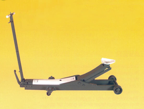
Weaver WA-73B Four (4) Ton Long Chassis
Hydraulic Service Jack
| MODEL | DESCRIPTION | KIT # | PRICE | |
| WA-72B | Two Ton Service Jack | KJ-106 |
|
|
| WA-72 Old | Two Ton Service Jack - Old
Style See Note # |
KJ-106-OS |
|
|
| WA-73B | Four Ton Service Jack | KJ-107 |
|
|
| WA-75B | Ten Ton Service Jack | KJ-108 | ||
| WA-85 | Twenty Ton Service Jack | KJ-109 |
|
|
| WA-140 * | Transmission Jack Cylinder Only | KJ-112 | ||
| WA-140 * | Transmission Jack Pump Only | KJ-113 | ||
| * Specify Suffix - None, A,B, or D | ||||
| # Note: Older style WA-72 Jack requires additional
parts. If the rear of the cylinder is a casting which is held down
by TWO Cotter Keys - it is an old style Order the following Additional Parts: Qty 3 ea S-7492 Packing 1-1/8" O.D. |
How Can I Identify My Jack?
Using the following Dimension Chart, - Compare Features and Measurements
| MODEL |
CAP. (tons) |
FRONT WHEELS |
SADDLE STYLE AND SIZE |
FRAME LENGTH |
JACK WEIGHT |
| WA-72B | 2 | Two - 4" Diameter | Triangular or Round 5"' to 6" |
51" | 136 lbs |
| WA-73B | 4 | Two - 5" Diameter |
Triangular or Round 5" to 6" |
58" | 212 lbs |
| WA-75B | 10 | Two - 7" Diameter | Round 9" |
66" | 356 lbs |
| WA-85 | 20 | Three- 7" Diameter | Square 7" |
69" | 531 lbs |
How Can I Identify My Jack Model Number?
Using the following Description Chart, - Determine Whether You Have an A or B
Model
| MODEL | CAP. TONS | CYLINDER DESCRIPTION | KIT # |
| WA-72A | 2 | Head of cylinder is held down
by TWO Cotter Keys |
KJ-106 |
| WA-72B | 2 | Head of cylinder is held down by Metal Tabs |
KJ-106 |
| WA-73A | 4 | Head of cylinder is held down by TWO Cotter Keys |
KJ-107 |
| WA-73B | 4 | Head of cylinder is held down by Metal Tabs |
KJ-107 |
| WA-75A | 10 | Head of cylinder is held down by A Large Pin Through The Frame |
KJ-108 |
| WA-75B | 10 | Head of cylinder is held down by TWO Bolts Inside Frame |
KJ-108 |
| WA-85 | 20 | Head of cylinder is held down by TWO Bolts Inside Frame |
KJ-109 |
If Your Jack Looks like a Weaver Jack, but it has a
different Manufacturers Label on it -
Some Manufacturers Private Label Weaver Jacks for sale under their Name -
Contact Us - We can assist you in Identifying your Jack.
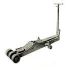
Weaver 20 ton Hydraulic Service Jack Model WA-85
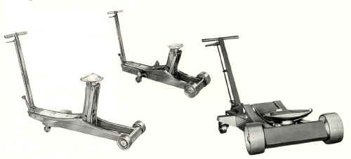
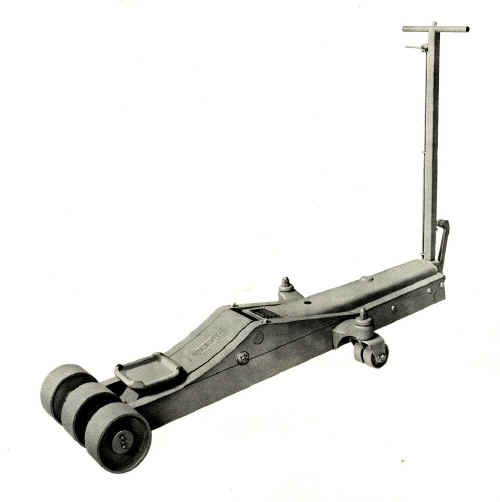
WA-72B (2 ton) WA-75B (10
ton) WA-73B (4 ton)
|
|
KJ-106 Seal Kit for Weaver WA-72B 2 Ton Jack |
KJ-107 Seal Kit for Weaver WA-73B 4 Ton Jack |
|
| Contains: S-6654 Piston Packing (3) S-22961 Cylinder Cap Gasket S-6016 Piston Ram Cup S-7265 Pump Cup S-7492A Pump Packing (3) 1-1/2"O.D.* S-17829 Large "O" Ring S-15047 Small "O" Ring S-2594 Ball Chamber Gasket S-2750 Ball 1/2" S-2505 Ball 5/16" S-2499 Cotter Pin (2) S-3234 Cotter Pin *Note: Older style WA-72 Jack requires additional parts. If the rear of the cylinder is a casting which is held down by TWO Cotter Keys - it is an old style Order the following Additional Parts: Qty 3 ea S-7492 Packing 1-1/8" O.D. (New Style is a Machined Block which is held down by Metal Tabs) |
Contains: S-6614 Piston Packing (3) S-22962 Cylinder Cap Gasket S-4714 Piston Ram Cup S-24648 Pump Cup S-7412 Pump Rod Packing (3) S-17829 Large "O" Ring S-15047 Small "O" Ring S-2594 Ball Chamber Gasket S-2750 Ball 1/2" S-2505 Ball 5/16" S-2499 Cotter Pin (2) S-3234 Cotter Pin |
|
|
KJ-108 Seal Kit for Weaver WA-75B 10 Ton Jack |
KJ-109 Seal Kit for Weaver WA-85 20 Ton Jack |
|
Contains: S-6615 Piston Rod Packing (3) S-22963 Cylinder Cap Gasket S-24649 Piston Ram Cup S-24648 Pump Cup S-7412 Pump Rod Packing (3) S-17829 Large "O" Ring S-15047 Small "O" Ring S-5125 Ball Chamber Gasket S-5122 Ball 5/8" S-3282 Ball 3/8" S-3083 Cotter Pin S-24703 Teflon Ring |
Contains: S-16022 Piston Rod Packing (3) S-22964 Cylinder Cap Gasket S-16023 Piston Ram Cup S-24648 Pump Cup S-7412 Pump Rod Packing (3) S-17829 Large "O" Ring S-15047 Small "O" Ring S-5125 Ball Chamber Gasket S-5122 Ball 5/8" S-3282 Ball 3/8" S-3083 Cotter Pin |
| INSTALLATION INSTRUCTIONS FOR WEAVER SEAL KITS | |
|
These Jack Cylinder Service
Kits are for minor cylinder repairs only, if additional servicing is
required have repairs performed by a qualified hydraulic jack repair
center. |
|
|
Use Safety Solvent or Mineral
Spirits to clean parts—blow dry with compressed air. Do not use Gasoline, lacquer thinner or any other solvents as these will damage the seals. |
|
| Use AW-32 Light Hydraulic Oil (or oil that meets MIL•F•17111 011 specifications) | |
|
|
|
|
To Remove The Cylinder
1. Remove the cotter pin
(pins) or bolts in the cross head.
2. Remove the cotter and pin
in the pump.
3. Remove the cotter and pin
in the release yoke.
4. Place cotter key in while
depressing foot pedal.
5. Raise the lifting arm by
means of the saddle bracket, and place a block of wood between the arm
and frame to hold up the arm.
6. This releases the cylinder
at the forward end, so that it may be removed as a complete unit, for
service. |
|
 |
|
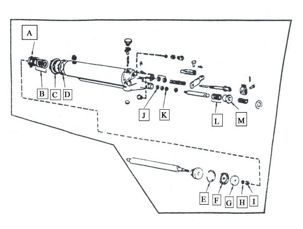
| Piston and Pump Assembly Derail for Weaver Jack Cylinders | |
 |
Ram Cup Replacement |
|
To Replace The Piston Ram Cup:
1. After removing the cylinder
unit as described above, place it in a vise.
Note that the vise jaws should
grip the steel block, not the
steel cylinder. Set the unit in the vise with the steel cylinder and
piston up. Remove the vent plug. Drain
the oil.
2. Remove the Packing Nut [A]
and three Packings [B] .Unscrew the cylinder cap [C] and lift the piston
out of the cylinder.
3. Remove the nut [I], Lock
Washer [H], and washer [G] which holds the cup [F] at the end of the
piston--put in the new cup [F], and replace the nut and washer.
(The Backup Teflon Ring [E] is
only used on certain – but not all WA-75A models only)
Either peen the threads with a punch or use a thread locking
compound to prevent nut from loosening.
4. In fitting the new cup into
the cylinder, USE GREAT CARE
as the cup passes the filler plug hole not to cut or otherwise damage
the cup. Lubricate the cup with
hydraulic oil when assembling.
5. Replace the Cylinder Cap
[C] and Gasket [D] -- install the 3 new Packings [B]
and the Packing Nut [A].
|
|
|
CAUTION
Excessive friction, chatter
and binding will occur if the cup nut is pulled down too tightly.
TIP
This means that you use only enough pressure to close the spring lock
washer [H]. Do not tighten
until the cup heel begins to extrude (swell) as this may cause problems
When servicing a jack with a
synthetic cup, it may appear that the nut has become loosened, but this
is not necessarily true. It is only necessary to hold the cup against
the ram with slight pressure to prevent leakage. |
|
 |
Pump Cup Replacement |
|
To Replace The Pump Cup (small cup):
1. Turn the cylinder unit pump
end upward in the vise.
2. Unscrew the packing nut [M]
- Remove three Packings [L] and pull out the pump plunger.
Remove the Nut [J] that holds
Cup [K] to the end of plunger; insert new cup, new packings and replace
the nut and washers. |
|
 |
|
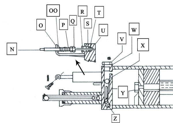
| Release Valve Group and Ball Valve Assembly Derail for Weaver Jack Cylinders | |
 |
Ball Valve Replacement |
|
Ball Valve Replacement
1. Remove the Ball Chamber
Plug [V]. Remove the Two
Balls [X&Z] and the Ball weight [Y].
2.
Reassemble with the two new Balls [X&Z], New Plug Gasket [W] and
Ball Weight [Y] (reuse the existing Ball weight).
Ball Weight is installed between the two balls.
IMPORTANT:
Whenever it is necessary to loosen or remove the Ball Chamber Plug, the
Gasket [W] should be replaced with a new one. Oil leakage at this point
is usually caused by trying to reuse an old gasket over again. |
|

|
Release Valve Packing
Housing "O"-Ring Replacement |
|
Release Group Needle Valve Packing “O” Rings Replacement
1.
Measure accurately the distance
from the Bracket [O] to the first Nut [P] on the compression spring.
Write this measurement down.
(This is approximately 2 inches)
2.
Loosen the Packing Nut [R].
Remove Nuts [P] & [Q], the Spring, the Valve Rod [N] , the Valve
Guide [OO] and the Packing Nut [R].
It is not necessary to remove the rod clevis.
3.
Remove the Packing Housing [S] and replace the two “O” rings
[T&U]. Now reinsert the
Packing Housing [S]. Reassemble
the Needle Valve and parts with the Packing Nut [R] tightly secured.
4. Tighten the adjusting nut
[P] to the original dimension
that you wrote down and lock this nut with Nut [Q]. |
|
 |
|
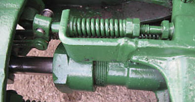
| Release Valve Group (upper ) - Pump Assembly (lower) | |
| Release Group - Needle Valve Adjustment | |
|
Release Group Needle Valve Adjustment:
In the release group
assembly, the spring governs the load that the Jack will lift.
When the pressure within the cylinder overcomes the spring
tension then the release valve floats off the seat.
It is Imperative that the release valve floats freely in the
release group assembly. To check- use your forefinger and thumb to grasp
the release valve where the release clevis pin passes thru, and wiggle
from side to side. There should be a minimum of .002 to.004 clearance in
the Release Vale Guide [OO]. If no movement is noted, follow these
steps:
Measure accurately the
distance from the Bracket [O] to the first Nut [P] on the compression
spring. Write this measurement
down. (This is approximately 2 inches)
Remove Nuts [P] & [Q],
the Spring, the Valve Rod [N] and the Valve Guide [OO].
It is not necessary to loosen the Packing Nut.
Next,
insert the Valve Rod [N] thru
the Bracket’s [O] opening, slide the
Release Valve Guide [OO] onto the rod, but not seated in the hole,
and insert the rod [N] into the Packing Nut’s [R] opening.
Gently
Tap the end of the release rod [N] with a hammer until it stays firmly
seated in the internal needle seat.
Slide the Release Valve Guide [OO] towards the Bracket [O]
(normally it will smoothly fit into the bracket hole) and then noting
where the center alignment of the rod in the bracket hole is off -- Tap
the welded bracket accordingly with a hammer to gently bend the bracket
and correct the misalignment. It is in alignment when you can smoothly
slide the Valve Guide into the Bracket’s hole.
Reassemble the Release Valve
and parts. Tighten the
adjusting nut [P] to the original
dimension that you wrote down and lock this nut with Nut [Q] and
then test the Jack for proper operation.
|
|
|
|
|
|
Troubleshooting See the Operations and Service Manual CLICH HERE |
|
 |
Print a
Copy of these Seal Kit Instructions CLICK HERE |


![]()
![]()
![]()
![]()
![]()
![]()
![]()
![]()
![]()
![]()
![]()
copyright 1997-2014
Castle Equipment Co.